
ANTENNA CONSTRUCTION - YAGIS
THERE ARE PLENTY OF SOURCES FOR DIMENSIONS - HERE'S SOME TECHNIQUES
ANTENNA CONSTRUCTION IN GENERAL
There are ample programs, websites, books and other sources for yagi dimensions. I am not going to contribute to a discussion of dimensions. This site details how I make my antennas with some different construction techniques and materials. I know there are people who think I'm nuts because copper is a lot more expensive than aluminium. If you consider the cost of running LDF4-50 up a tower and N connectors for the same, a couple of hundred bucks for a good, weather proof antenna is nothing.
COPPER v ALUMINIUM
At frequencies of 144MHz and over, very high gain antennas can be made quite small. There doesn't seem to be any need to make such small antennas out of Aluminium. I make mine out of copper. Even if you don't like the expense of making the entire antenna out of copper, there are advantages in making the radiator at least out of copper. If it is properly hardened, any thickness of copper will hold itself up for a couple of metres. Because the antennas are so small, you don't need much of it and so expense isn't much of a problem. Copper has quite a few advantages over Aluminium (in the order I find them to be):-
1) Copper can be soldered, Aluminium can't.
2) Copper can be joined back together easily if you make a mistake or want to reuse offcuts or recycle old antennas.
3) Copper can be softened (annealed) for bending and hardened easily.
4) It is easily available from plumbing supply stores in any size from 6mm to hundreds. I get mine from Scott's plumbing supplies. (Adelaide South Australia).
5) Even annealed copper conducts half again better than Aluminium.
SIMPLE ANTENNA FOR 70CM (AND ABOVE)
I had some PCB off-cuts and thought I would try to put them together to make an antenna. Someone asked what I was doing and told me there was already an article in an AR magazine. (Yes Dene - that was you.) I have not seen the article and have no idea what it looks like but here's mine.
This antenna is extremely light in construction and is not suitable for 2m. The boom is made from 10mm strips of double sided PCB material. Where the copper needs to be removed I did it with a light touch with an angle grinder. There are only 6 elements, 1 reflector, 1 driven and 4 directors.
The boom is made out of two such strips of PCB material and the elements made from 2mm copper wire. The PCB strips are soldered in a T pattern as shown here. The grinding and hole drilling were done after it was soldered together.
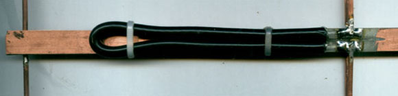

Only the reflector and driven element (a folded dipole) are shown.
(Note, you don't have to solder it all the way along. A few dabs will do.)
When matching with pieces of coax, it is often necessary to keep the bend smooth and wide but here quite unnecessary. The matching loop is ½λ long meaning each side is ¼λ. The impedance transforming effects of a ¼λ of coax to the open end are such that the bend doesn't matter much.
The elements are connected to the boom, which is so thin its effects are negligible, by drilling holes and soldering. The only exception is the driven element which is soldered to the boom with appropriate pads on the copper on the connection side and into a small V cut in the PCB on the other.
There is a virtual ground half way along the elements anyway. This is not meant to be a high performance antenna although it works better than I expected.
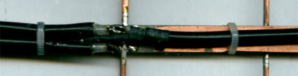
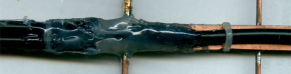
The centre of the coaxial cable tail is connected to either one side or the other (since it is otherwise symetrical) and the other side to the ground (coax outer of ½λ matching section) between the two ends of the coax as close to the coax ends as possible. Finally the whole thing is gooped up with holt melt glue.
OTHER (PROPER) ANTENNAS
THE BOOM AND MOUNTING THE ELEMENTS
Some people will feak out when I say I use 25mm square steel for the boom but you should read the rest of this first. The idea of using a cylindrical boom is to minimize its effects but if the standoffs described here are used, the effects will be less than if the elements are connected to the boom or laid against it.
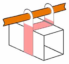
The elements are held by using small pieces of either double or single sided PCB with the section holding the element etched away. These can be drilled to a tight fit for the element and soldered to a cross piece as shown below. The black line shows the half way point while the coloured section shows where the copper should be left in tact. This allows assembling the standoffs by soldering.

The hole size and other dimensions should be made to suit the boom and element size. In addition to the shapes above, a square section needs to be made to suit the width of the boom.

 OR
OR
The standoffs can be held in place along the boom by either using some sort of glue or with a small screw in the side. An alternative is to solder a piece of bare copper wire from one side to the other under the boom. If it soldered on one side first then pulled tight while it is soldered onto the other, it will stay in place quite well. Either a bit of hot melt glue over the wire under the boom or a bit of superglue under the board on top will hold things quite firmly. This has the advantage that, if you want to try some other dimensions, all you need is a soldering iron and some acetone (used at different times and kept away from each other).
If care is taken when drilling the holes and a tight fit for the element achieved, the element can he held quite firmly in place with some sort of glue. I use good quality cyanoacrylate. This can be obtained from hobby shops speciallising in models. I then use a bit of some extra holt melt as well just to make sure.
With this arrangement, the element is completely insulated and isolated from the boom. The effects of the boom will be almost eliminated because the element doesn't come anywhere near it.
THE BIGGEST ADVANTAGE THOUGH IS THAT, IF SOME SORT OF GLUE IS USED INSTEAD OF THE SCREW, YOU CAN EASILY ADJUST TO OTHER DIMENSIONS WITHOUT ALL THE DRILLING. If someone comes up with a new and better design it is easy to change. It is quite easy to remove cyano-acrylate with acetone. The good stuff will hold the elements in place quite firmly. If you use holt melt glue, all you have to do is warm it up.
WORKING WITH COPPER
HARDENING AND SOFTENING
Copper tubing comes in two forms, annealed or hard. From 6mm to 13mm it generally comes in annealed only. At or around 13mm it comes in both forms and above it comes in hard only. The annealed copper can be made hard by work hardening, that is, bending it. The hard copper can be annealed by simply heating it to red heat then cooling it. Although it is useful, there is no need to have oxygen bottles and these days plumbers use mapp gas. In sizes up to 13mm or even 20mm, a good gas torch will do. While you are getting the copper tubing at the plumbing supply store, pick up some 2% silver solder as well, not the stuff you use with a normal soldering iron but the hard stuff plumbers use.
STRAIGHTENING ANNEALED COPPER TUBING
Annealed copper tubing in the small sizes is usually shipped in rolls. To make an antenna, it usually needs to be straight. The first step I take is to hold one end of the roll in a drill vice with a couple of bricks on top and simply roll it out onto a reasonably flat surface. This, of course, is by no means straight enough yet but is good enough to fiddle around for a little while then measure and cut element lengths. Make them a few mm too long. Its easier to adjust them with a fine grinder later than make them longer.
Place one end of the annealed copper element into a cordless drill. Holding the drill in one hand, grab hold of the element with your other hand using a leather glove or piece of cloth. I put some polish on at the same time. Rotate the dril SLOWLY and run your thumb along the element from the drill chuck to the end giving the element a SLIGHT bend as you go. Don't bend too much to start with nor rotate the drill too fast or a spiral can form. To further avoid this, reverse the direction of the drill every few runs. After a half a dozen runs along the element, place the other end in the chuck and repeat the operation. Even after the element is straight, a few more runs will work harden the element helping it conduct better and stand up with a large bird sitting on it.

All text and images on this site are Copyright to John Langsford (vk5ajl).
You may provide links on other sites or use the information and pictures for your own personal use.
You may use the text or images for redisplay or quotation provided you acknowledge the source ie. vk5ajl.com.
I think that's pretty fair, don't you?